What is Cisco Packet Tracer?
Cisco Packet Tracer is a comprehensive networking simulation software tool for teaching and learning how to create network topologies and imitate modern computer networks.
Definitions needed to understand what follows
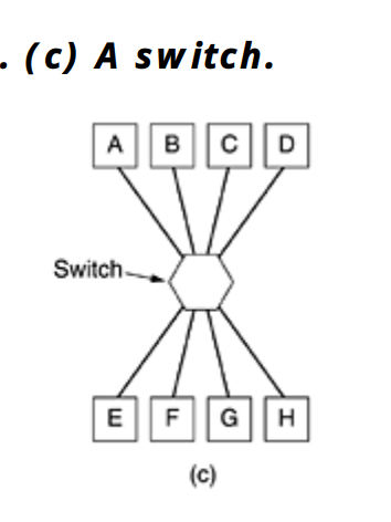
What is a Swtich?
a switch is most often used to connect individual computers, as shown here:
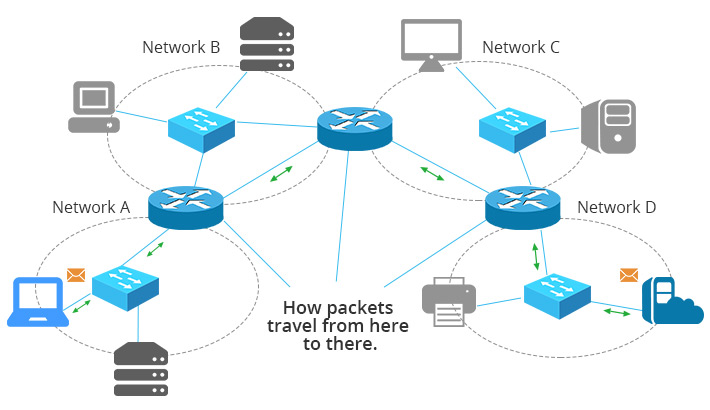
What is a Router?
A router directs data between networks, connecting devices and enabling communication by choosing optimal paths for data transmission.
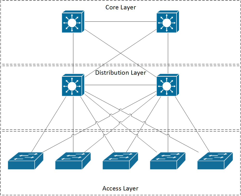
What is a Multi-Layer-Switch
A Multi-Layer Switch combines Layer 2 (switching) and Layer 3 (routing) functions, enabling faster routing within VLANs and between networks.
Note that understanding this basic explanation about each equipment seen here, as well as the notion of addressing, that is, each equipment is addressable (mac or ip), will help make the creation and configuration of network topologies easier to understand.
Key Concepts Viewed
1. VLANs
VLANS are best explained by the the following example
Say there is a company building which contains many departments: Finance, Research…etc.
It would make sense that the research department will often NOT want to share information with its neighboring Finance department. In a normal setting, the separation has to be physical, but with the help of virtual LANs, the separation can be logical.
VLANs are based on specially-designed VLAN-aware switches, although they may also have some hubs on the periphery, as in Fig. 4-48. To set up a VLAN-based network, the network administrator decides how many VLANs there will be, which computers will be on which VLAN, and what the VLANs will be called.
EXAMPLE
Achieve the following network topology using cisco packettracer.
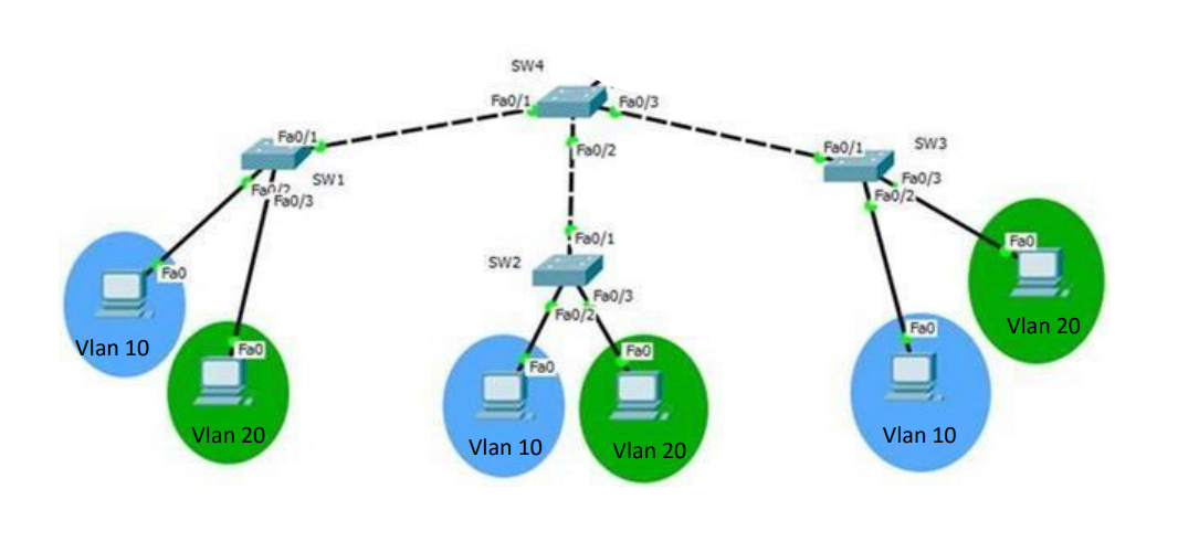
- First, copy paste the topology (no commands, use icons).
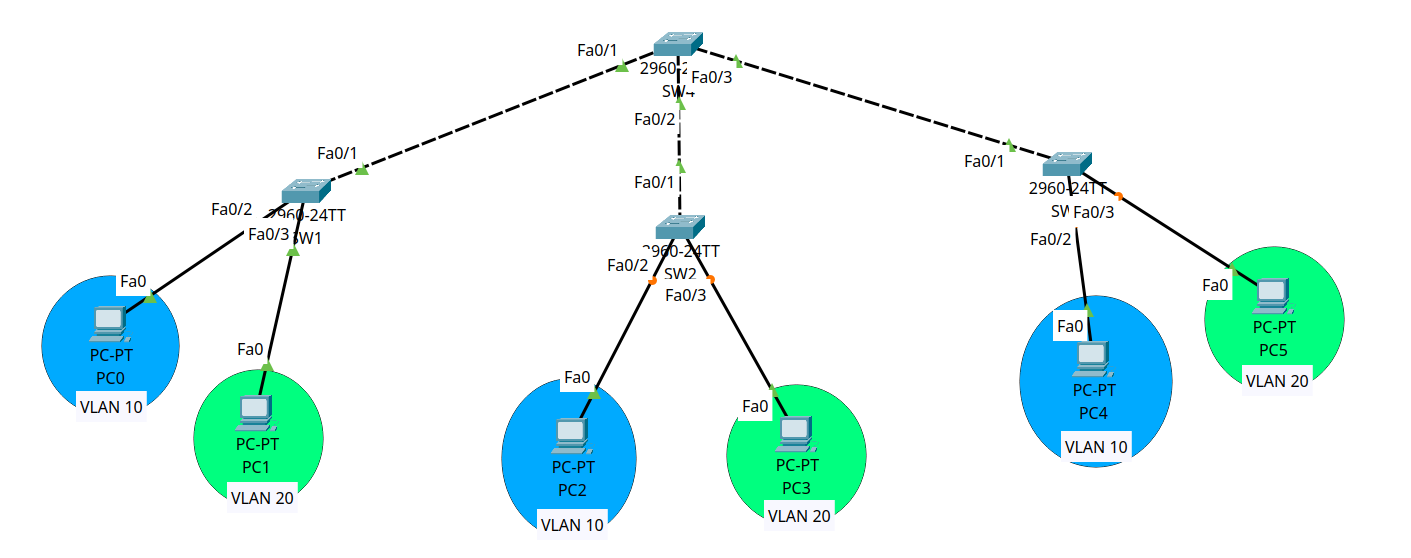
- Create the VLANs and assign descriptive names to them.
Switch(config)#vlan 10
Switch(config-vlan)#name blue
Switch(config-vlan)#exit
Switch(config)#vlan 20
Switch(config-vlan)#name green
Switch(config-vlan)#exit
To see if you are correct, type
show vlan
- Configure trunk ports (between switches) to carry VLAN tags for inter-switch communication and access ports (between switches and end devices) to assign devices to their respective VLANs correctly.
# for trunk interfaces
Switch(config)#interface fastEthernet 0/1
Switch(config-if)#switchport mode trunk
Switch(config-if)#switchport trunk allowed vlan 10,20
Switch(config-if)#exit

# for access interfaces
Switch(config)#interface fastEthernet 0/2
Switch(config-if)#switchport mode access
Switch(config-if)#switchport access vlan 10
Switch(config-if)#exit
To see if you are correct, type
show interfaces trunkorshow vlan brief
Assign IP Addresses to the end-devices (use GUI, no CLI).
Test connectivity using the ping command (It should work).
The document covers more than what was discussed here. It covers:
- Native VLAN: Configures untagged traffic on trunk ports.
- VLAN Management: Assigns an IP address to a VLAN for remote management.
- Password Configuration: Secures access to the switch via console and VTY.
- Saving/Deleting Configurations: Saves or resets the switch configuration.
- VLAN Deletion: Removes a VLAN from the switch.
- VLAN Creation and Naming: Creates and names VLANs.
- Configuration Verification: Verifies the switch’s configuration status.
2. VLANs Using a Multi Layer Switch
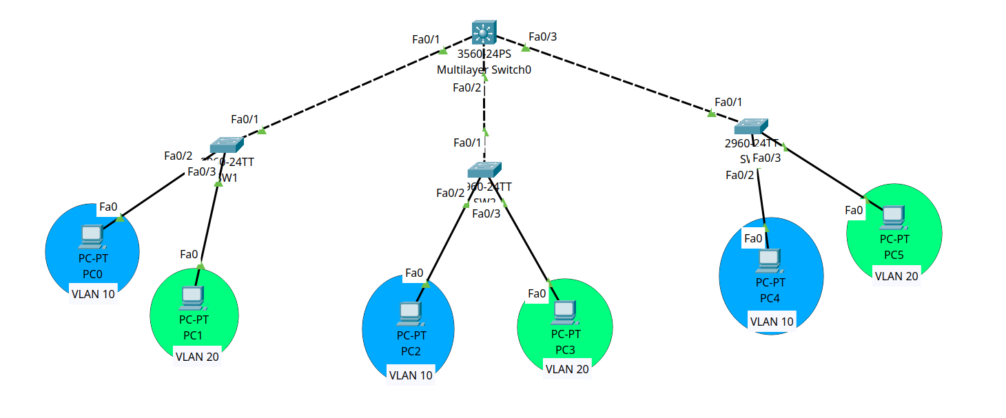
The goal is for one end-device in one vlan to communicate to another end-device in another. We keep the same configuration for the three switches and their interfaces, and we configure the layer 3 switch as follows:
Create the VLANs (as shown previously)
Switch ports to mode trunk and allow vlan 10 and 20.
Switch(config)#interface range fastEthernet 0/1 - 3
Switch(config-if)#switchport trunk encapsulation dot1q
Switch(config-if)#switchport mode trunk
Switch(config-if)#switchport trunk allowed vlan 10,20
Switch(config-if)#exit
- Create VLAN interfaces inside the SVI and assign IP addresses to them.
Switch(config)#interface vlan 10
Switch(config)#ip address 192.168.10.10 255.255.255.0
Switch(config)#exit
Switch(config)#interface vlan 10
Switch(config)#ip address 192.168.10.10 255.255.255.0
The multi layer switch will use the network address of the assigned IP to consult its routing table to route the packet to its destination.
- Enable routing on the Layer 3 Switch to route inter-vlan traffic.
Switch(config)#ip routing
Link end-devices with the switch by modify their default gateway to match the address assigned to the VLAN interface of the SVI (use gui).
Test connectivity between two devices from diffrent VLANs.
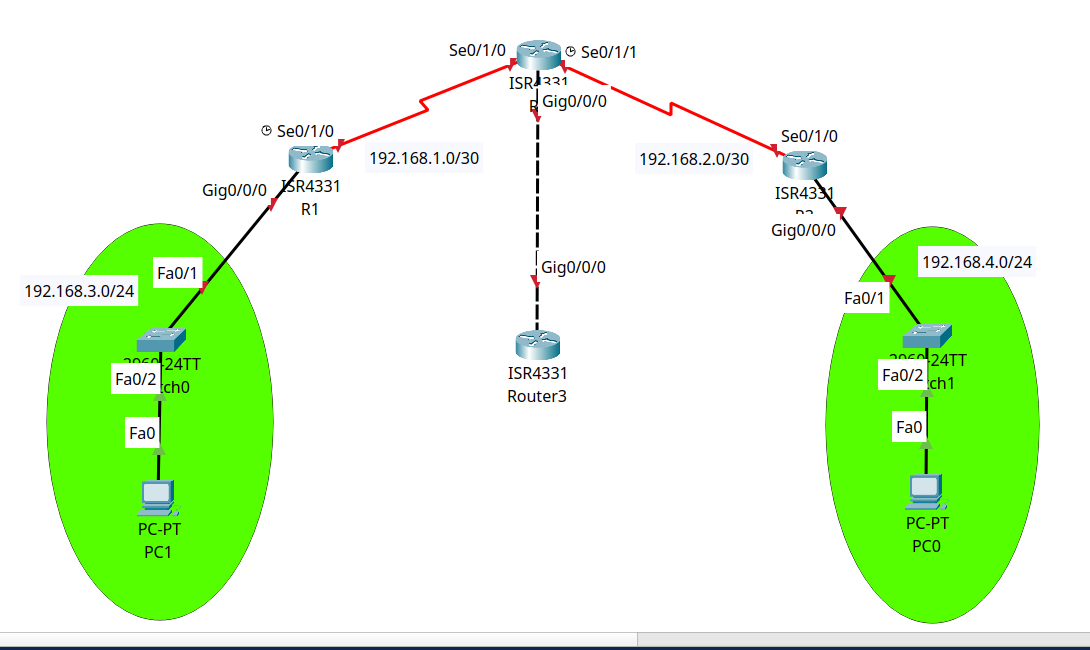
3. Routing
The network layer is concerned with getting packets from the source all the way to the destination. Getting to the destination may require making many hops at intermediate routers along the way, thus requiring a routing procotol.
We can either define our routes statically (1st routing TP), or dynamically (2nd TP), but overall, our job or the routing protocol’s is the same: Provide the information necessary to move the packet from one router to another to ultimately reach the destination.
you need to add NIM-2T (Network Interface Module - 2T) or a similar serial interface module to your routers in Cisco Packet Tracer to use serial connections.
Make sure you copy this topology before proceeding.
Static Routing
Static routing involves manually configuring routes on each router to define explicit paths for network traffic.
- Assign IP Addresses to Interfaces:
# for each router, change the interface-id and addr with those correct
# these are for direct connection.
Router(config)#interface gigabitEthernet 0/0/0
Router(config-if)#ip address 192.168.3.1 255.255.255.0
Router(config-if)#no shutdown
Router(config-if)#exit
- Add Static Routes:
# Syntax: ip route <network-address> <subnet-mask> <next-hop-ip | exit-interface>
Router(config)#ip route 192.168.4.0 255.255.255.0 192.168.1.2

# static routing (optional)
Router(config)#ip route 0.0.0.0 0.0.0.0 192.168.1.2
To verify routing use the command
show ip route
- Test connectivity using the ping command (You have to assign each device an IP addr + default gateway).
Note that the default static route has be unique accross your topology or problems will occur.
Dynamic Routing
We’ll use the RIP protocol which shares the information of routing accross gateways participating in the routing mechanism through a multicast address.
To setup this dynamic routing, remove the static routing (keep only those directly connected):
#no ip route ...
Then follow these steps:
- Activate the RIP Process, set the RIP version and disable Auto-Summary for each router participating in the protocol.
Router(config)#router rip
Router(config-router)#version 2
Router(config-router)#no auto-summary
- Declare networks directly connected to the router.
Router(config-router)#network 192.168.1.0
Router(config-router)#network 192.168.3.0
- Advertise a Default Route
# in the router that the default route is defined at
Router(config-router)#default-information originate
- Test connectivity using the ping command (give router a bit of time to share the routing information between each other)
4. Bonus (Inter VLAN Using a Router)
Copy the topology of the first VLAN TP and add a router like this:
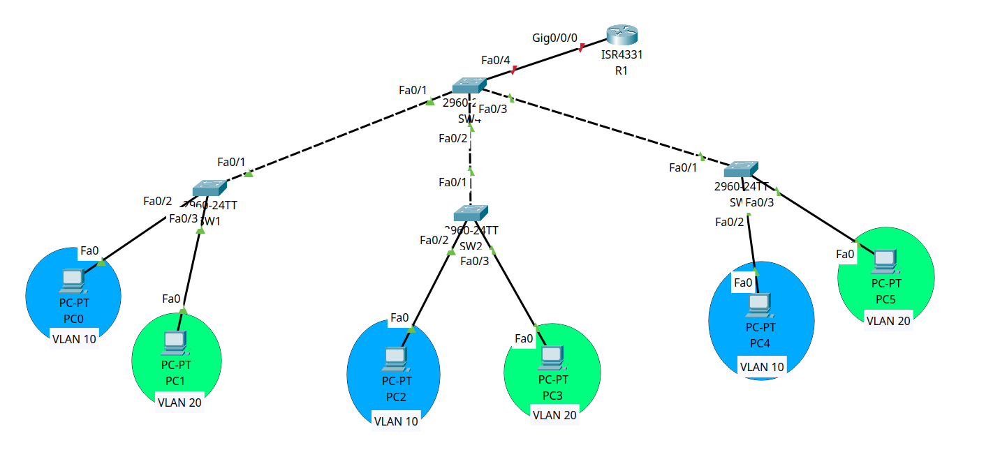
- Router Configuration for Inter-VLAN Routing:
Router(config)#interface gigabitEthernet 0/0/0.10
Router(config-subif)#encapsulation dot1Q 10
Router(config-subif)#ip address 192.168.10.10 255.255.255.0
Router(config-subif)#exit

# after configuring each and every one:
Router(config)#interface gigabitEthernet 0/0/0
Router(config-if)#no shutdown
Router(config-subif)#exit
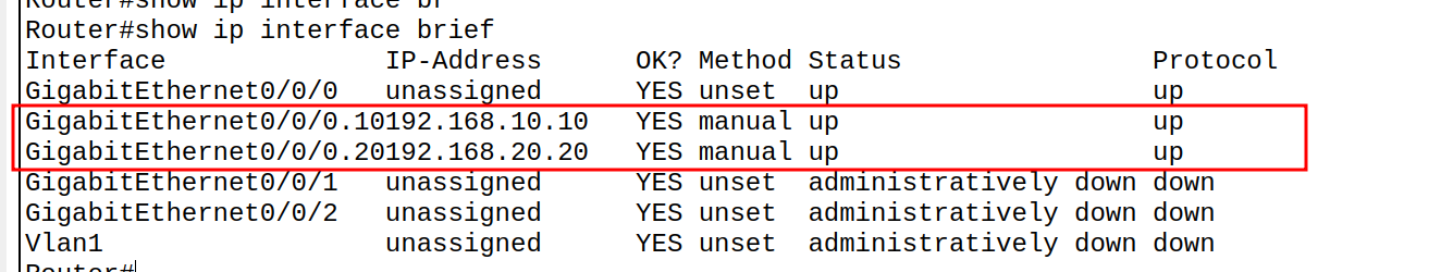
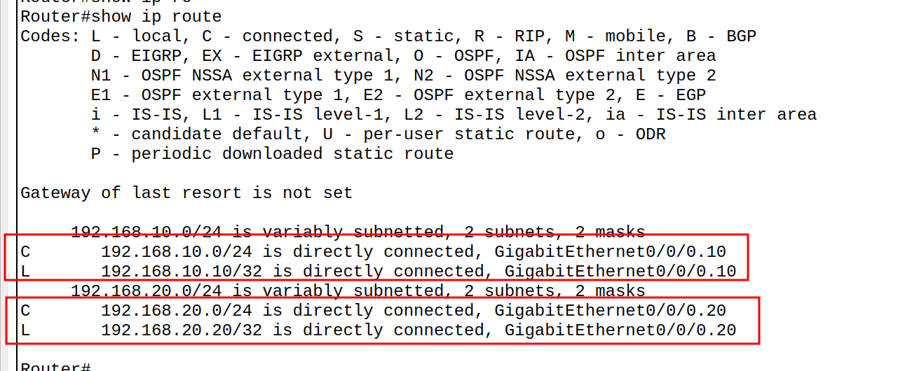
You can make sure the subinterfaces were created using
show ip routedon’t forget to make the 4th switch interface to be trunk.
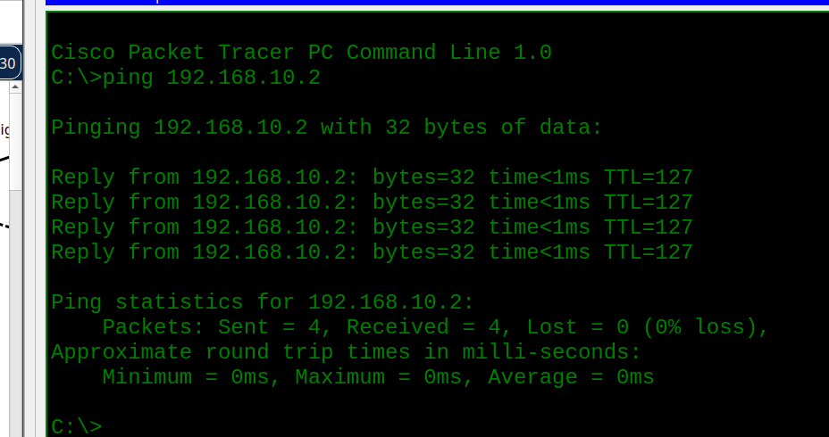
- Test connectivity using the ping command between different vlans.
- Show Router Configuration
- To clear the ARP table:
- On the switch/router:
enable
clear arp-cache
- On the PC:
arp -d
Summary
Good Luck~